Skip to content

Instantly share code, notes, and snippets.

@X3msnake
Last active December 27, 2024 11:45
Show Gist options
  • Save X3msnake/ed5337bb6b21dc5c40036b204968dfd4 to your computer and use it in GitHub Desktop.
Save X3msnake/ed5337bb6b21dc5c40036b204968dfd4 to your computer and use it in GitHub Desktop.
Antminer Beaglebone S5 - hack to use linux research

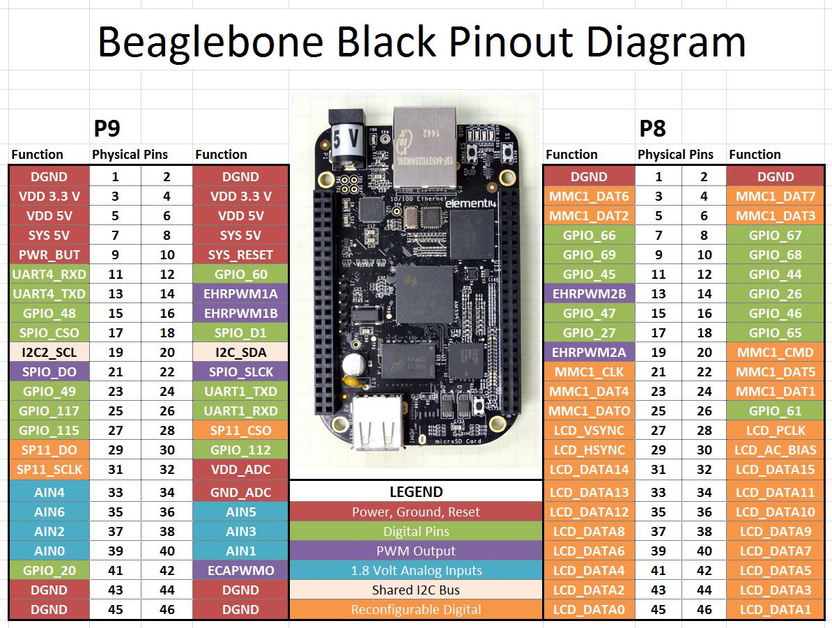
BeaglePinout BeagleSerialPins-LED Meanings Power Jack Flashing-a-Beagle

erase emmc manually: https://e2e.ti.com/support/legacy_forums/embedded/linux/f/linux-forum-read-only/398780/script-to-erase-emmc-independently-beagle-bone-black

Online board view (click image for link)

image


Beagle Reference Manual

Images

Debugging Putty

JTAG

Backup and Flashing

Resetting the root password

Bootloader

About DTS files (Device Tree Blob - Flat Device Tree)

Micron NAND Flash Memory (S5 Antminer)

Could not probe the EEPROM; something fundamentally wrong on the I2C bus.

https://e2e.ti.com/support/processors/f/791/t/297989?AM335x-EEPROM-disable

Power quick flahs - Dead from bad probing

https://www.element14.com/community/thread/41564/l/element14-branded-beaglebone-black-wont-power-on?displayFullThread=true

NAND reading with arduino

https://hackaday.com/2017/03/10/arduino-into-nand-reader/ https://www.j-michel.org/blog/2014/05/27/from-nand-chip-to-files

CAPES

@X3msnake
Copy link
Author

X3msnake commented Jun 9, 2022 via email

@AdamM68
Copy link

AdamM68 commented Jun 9, 2022

:( so antminer is going to a dustbin . sad

@Demianra
Copy link

Demianra commented Jul 7, 2022

Have You solved the problem how to flash linux(debian) to Antminer BBB ? I have one antminer BBB, soldered switch to S2, hold S2 during powering and ....it is still loading antminer software :( Have You found any trick ?

Read mi post from Jan 04, i can boot debian 7.5 from a SD, isn´t perfect but maybe works for your project.

Here the link with Debian 7.5

https://debian.beagleboard.org/images/bone-debian-7.5-2014-05-14-2gb.img.xz

User "root" without a password.

@Ga-Ol-St
Copy link

Ga-Ol-St commented Mar 15, 2024

Additional updates about board which I did found by hardware and software investigations and digging documentation.

All information which I will put here is relevant for old boards BB_V1.4 and BB_V1.5 sourced from old Antminers S5.

I have them on hand and did test this and burn 1 of them during hardware investigation :-)
Judging by photos this information should be relevant for earlier boards and probably latest,
But you should understand that if you fry your board - it's your fault :-)
My Goal is to give them a second life with latest Debian for different tasks like drive 3D printer with klipper, do RS-485 MQTT bridge, use them in home automation, data logging, etc ...
I still have 8 of them alive.

Basic statements:

  • "Boot" button will not help you without additional tweaks.
  • Board based on AM3352 Cortex A8 CPU (this CPU don't have additional PRU cores as AM3358)
  • Board have 512Mb DDR3 memory
  • Board uses NAND flash with 256Mb memory (2Gbit size) and it's partitioned to 9 partitions (SPL, 3xSPL backups, U-boot, Bootenv, FDT, KERNEL, ROOT, CONFIG)
  • I went thru all the hell to do full NAND restoration successfully - but it's not worth it when uSD is quicker and cheap.
  • Board don't have EEPROM
  • Board can work without Hashing control board.
  • Board have PCB RevB5 - it can be seen thru black silk screen on back side under missing power input, but not sure if it's truth.
  • Board don't have Barrell power input but it can be soldered, or you can use pins (P9_01+P9_02) as a GND and (P9_05 + P9_06) as +5v power input
  • Board require 5v, 1A DC power, but usually consuming only 0.1-0.2A
  • Board have Auto-start, if it's see power - it will try to start for 5 sec, if CPU hardware can't start - PMIC will shutdown itself.
  • To see some results you need Serial connection to board, if pins are missing - add them (only 3 needed ) connector J1, pins 1(Gnd), 4(rx), 5{tx)

More serious details and workarounds.

Why boot button is not helping ?

When you press (or short) boot button it should change boot order by putting SYSBOOT[2] flag to a low state,
it's doing this by connecting GND and LCD_DATA2(P8_43) pin via 100oHm resistor (R75)
(connection GND->BOOTBTN->R75->LCD_DATA2)
but that LCD_DATA2(P8_43) pin in Antminer boards is already in low state, so button don't have any effects.

Boot description

From factory this board have following hardwired boot flags: SYSBOOT[4:0] = 10011h
Which setting board to this boot order: NAND NANDI2C MMC0 UART0
So the board always loading first stage loader from NAND device, if NAND is there and in good shape then first stage loader will start (SPL U-BOOT), SPL will load second stage loader (Main U-BOOT).
When main U-Boot is progressing it will search for uSD card and if found it and considered a valid - it will start loading from there, if it's considered invalid - it will continue boot process from NAND.

If NAND is not in good shape - you stuck, SPL not loaded and board doesn`t show anything on Serial console, just Red LED will be glowing this indicate that second power rail (VLDO2) of TPS65217C is working.

How to tweak boot button and boot order

There are 2 options: permanent and temporary.
Permanent: move resistor from R93 (Front of a board, around P8_41 pin) to R68 empty place (Back of a board, around P8_41), this will make SYSBOOT[2] High by default and will switch default boot order to SYSBOOT[4:0] = 10111h
new default boot order: MMC0 SPI0 UART0 USB0
If button will be (pressed) shorted - you will get old vanilla boot order: NAND NANDI2C MMC0 UART0

Temporary solution: you can temporary switch that SYSBOOT[2] flag by pooling P8_43 to High state,
for that you need a peace of wire and 1K (1000 oHm) resistor.
Power off the board and create following connection
P9_03(+3.3v)------wire------1k resistor ----wire ------- P9_43(LCD_DATA2)

After you get new boot order and try to start board without uSD card in serial console you should see that board is constantly sending "C" characters - this is a good sign that you did switch boot order, board didn't found uSD and SPI sources and vent to UART Boot mode, BTW This UART mode can be used to boot without uSD card at all.
Now if you did permanent solution - you can short boot button and give power - board will be booting from NAND.
If you did use temporary solution - you can remove it and board will return to old style boot from NAND.

Now when you have Full uSD loading capabilities - you can try different images, but many will not work :-)

Why many images don't want to load:

Simple answer - they can't recognize your board.
Board don't have EEPROM which is storing information about board type and hardware revision so Bootloaders refusing to load, if you will add EEPROM chip U7 and 2 additional missing components R156 and C152, then write to EEPROM board data from BeagleBone black - almost all images will start trying to boot (you will see boot sequence) but most probably they will die in process because of trying to access eMMC flash which is not there.

Why some images can load without EEPROM

Simply because they don't care at all and always loading single hardware definition, usually this kind of images are referenced as "Custom board images", but they can be unstable because hardware definitions which was put in that image can be incompatible or interfere with your board.

Where to get good image for booting

There are 2 options,
First options just search and tryout, most probable candidates should have support for NAND flash and am335x CPU or which don't have eMMC support at all - This board is using good portion of pins for NAND flash which are usually used for eMMC flash - so here is a conflict,
Second option is to build your own "Custom board image" anyway you like (Buildroot, Yocto, etc..) but be sure that you did apply special patches which are disabling EEPROM detection and using some "default" board, then add hardware definition (DTS) to that "default" board. Then compile, build, create uSD Image and try it out. Currently I have a work in progress to create custom image with U-Boot 2023.10 and Debian 11.7 (Kernel 5.10.162), but still there are some issues with hardware definitions which make Kernel to die, when I will have stable image - I will post it, But don't wait for it from me - my nerves are on edge from this.

Where to get correct hardware definitions for board (DTS - Device tree source)

You can extract it from uSD images for corresponding Antminer, usually these boards default to "A335BLNT" board name when system try to detect it, Then U-Boot is loading corresponding DTB file for this kind of board, those DTB files are located on second partition, or analyze your U-boot environment to understand where it's getting this file. Don't be fooled by filename like "am335x-beaglebone.dtb" or "am335x-boneblack.dtb" - yes their content have some parts from "beaglebone" or "beaglebone black" but those files are custom builds with additional stuff like "i2c" bus with "asic-board" hardware in it (Hashing control board). When you will get that DTB file you can decompile to human readable format with "dtc" tools.

Sources of information

Most information was obtained form TI documents and BeagleBone forums, docs, schematics.
some documents and links:
"AM335x and AMIC110 Sitara™ Processors Technical Reference Manual"
"AM3352 datasheet"
https://www.ti.com/product/AM3352
https://github.com/beagleboard/beaglebone-black (use TAGs to get access to old revision)
https://github.com/bitmaintech/Antminer_firmware
https://elinux.org/BeagleBoardRecovery

I hope this info will help somebody to move further or it will help to unbrick the board.

Sign up for free to join this conversation on GitHub. Already have an account? Sign in to comment